
Ready to Upgrade Your Lighting?
Get help choosing the right AEON LED solution for your field, facility, venue, or outdoor space.


A high-mast lighting system should not be selected by wattage or a generic pole-spacing chart. The correct design depends on the site geometry, mounting height, required illumination, optic distribution, fixture quantity, structural conditions, wind exposure, maintenance access, controls, and acceptable light beyond the property.
A project-specific photometric layout is needed to evaluate how these factors work together. The pole, foundation, electrical system, and mounting assembly must also be reviewed separately by the appropriate qualified professionals.
The answers are specific to the site. A configuration that works for a roadway interchange may be inappropriate for a seaport, airport, industrial yard, parking area or correctional facility.
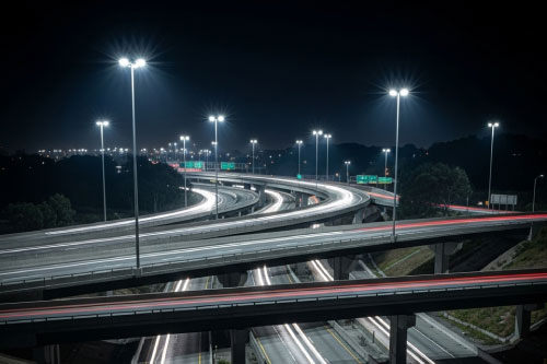
High-mast lighting generally refers to a group of luminaires mounted on a tall pole to illuminate a large area from one elevated location. Common applications include roadways, interchanges, airports, seaports, rail yards, parking areas, industrial facilities, storage yards, and other expansive outdoor properties.
However, there is no single height that defines every high-mast system.
For example, the Federal Highway Administration has defined high-mast lighting as luminaires mounted at approximately 20 meters (about 66 feet) or higher. The Texas Department of Transportation defines high-mast roadway lighting as having a mounting height of 100 feet or more. Commercial lighting projects may use the term more broadly.
Because definitions vary, the project owner and design team should confirm which standards, specifications, and authority requirements apply to the particular site.
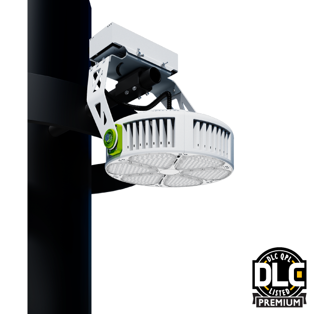
For a broader introduction to applications, visit AEON’s guide to high-mast lighting applications. To review available product families, beam distributions and high-output options, visit the AEON high-mast lighting product page.
The quality of a lighting layout depends on the quality of the information provided. Missing or inaccurate site information can result in a layout that appears acceptable on paper but does not reflect the final installation. The design team should collect the following information before selecting luminaires or estimating fixture quantities.
Provide a scaled plan showing property boundaries, roads, buildings, storage areas, rail lines, loading zones, parking, fences, utilities, shoreline boundaries, equipment, and permanent obstructions.
CAD files are helpful, but a clearly dimensioned PDF may be sufficient for an initial review.
Identify which areas must be illuminated and which should remain dark. Separating the site into functional zones (e.g., active loading vs. storage or perimeter) helps prevent unnecessary wattage and overlighting.
Base the layout on defined criteria: average/minimum/maximum illuminance; uniformity ratios; vertical illuminance; glare limits; property-line limits; uplight restrictions; CRI and CCT; and camera requirements.
Document pole locations, heights, materials, fixture counts, ring/crossarm details, current wattages, foundation info, and structural condition. Do not assume existing poles are suitable without structural review.
Collect available voltage, circuit/panel capacity, branch wiring, grounding/bonding, fixture wattage, control wiring, disconnects, surge protection, and communications infrastructure.
Verify product ratings for salt air, coastal exposure, chemicals, dust, moisture, vibration, extreme temperatures, flooding, washdown procedures, corrosive materials, or sensitive wildlife areas.
Determine wind speeds, exposure categories, local codes, pole heights, fixture weights, Effective Projected Area (EPA), ring/crossarm configurations, ice loading, and soil/geotechnical conditions.
Include nearby homes, hotels, hospitals, roads, airports, waterways, habitats, businesses, property lines, and windows in the photometric model to evaluate spill light and glare.
Document operating hours, after-hours modes, security settings, emergency operation, dimming needs, zoning, remote access, astronomical clocks, and system integration.
Plan maintenance during design by confirming use of lowering rings, fixed mounting, bucket trucks, cranes, walkways/platforms, ground-level service gear, or remote driver locations.
Mounting height changes the geometry of the entire lighting system. A taller mast can potentially distribute light over a larger area, but greater height does not automatically create a better or more efficient design.
A higher position increases the visible area per luminaire and may reduce total pole count, but output at the target surface must be maintained.
As height and horizontal throw increase, designers need concentrated optics so usable light reaches the target effectively.
Taller masts can replace multiple shorter poles but may require higher-output luminaires, different beam distributions, and stronger foundations.
Greater height makes luminaires visible from farther away. Aiming angles, shielding, and topography must be modeled accurately.
The complete assembly—pole, parts, luminaires, lowering gear, and foundation—must account for wind speed, weight, EPA, and soil data.
Ensure ground clearance for lowering rings. Masts near airports/heliports may require Part 77 FAA OE/AAA pre-screening.
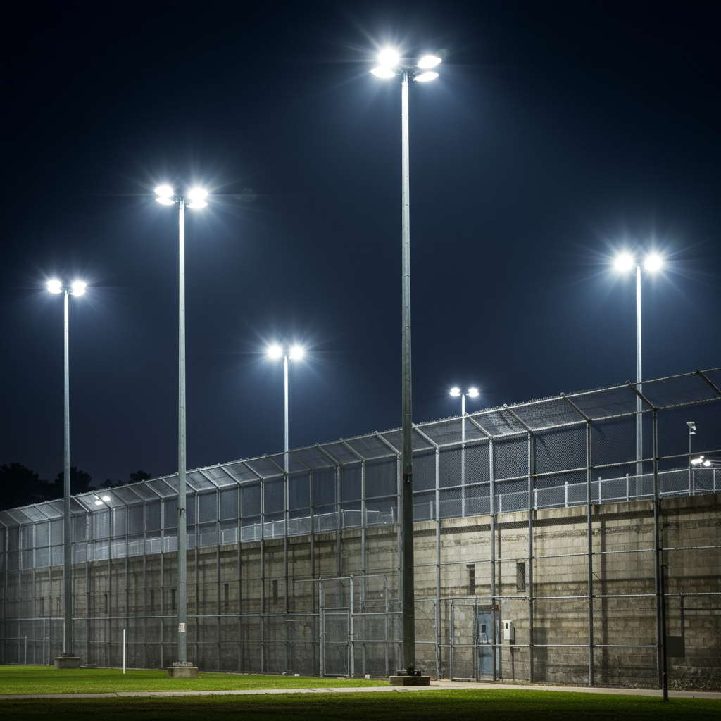
There is no universal high-mast pole-spacing formula that works for every application. Published spacing examples from transportation agencies are developed for specific pole heights, roadway configurations, optics, fixture quantities, and target criteria. They should not be copied into an unrelated industrial, commercial or municipal project.
High-mast pole spacing depends on mounting height, site geometry, placement restrictions, fixture output, optics, orientation, illumination criteria, uniformity, obstructions, terrain, light-loss, spill-light limits, and maintenance access.
During photometric design, coverage from adjacent poles is overlapped until calculation grids meet requirements. The correct spacing satisfies complete performance criteria—not just the greatest distance that produces a visible patch of light.
The optical distribution determines where a luminaire sends its light. Selecting the correct distribution is more important than comparing total lumens alone.
Distributes light in a similar pattern around its central axis. Ideal for open areas surrounding a central mast, large square target zones, or balanced multi-directional coverage.
Directs more light in one specific direction. Ideal for roadways, long storage lanes, property edges, loading zones, and rail yards where light must push forward without backward spill.
Concentrates intensity for long distances but can produce bright spots or aiming sensitivity. Long-throw designs frequently combine multiple distributions rather than using a single optic.
Lumens measure total output, not direction. A lower-lumen fixture with the correct optic often delivers more usable light to the target than a higher-lumen fixture with an unsuitable distribution.
Photometric Files and Final Aiming: The design must use exact luminaire photometric files (output, optic, driver, mounting). Final aiming and rotation parameters must transfer accurately to installation documents to prevent field errors.
Fixture quantity cannot be calculated accurately from site area and lumens alone. Quantity must be tested in a photometric model using the proposed luminaire, optic, mounting height, orientation, light-loss assumptions, and project criteria.
The goal is not simply to use the fewest luminaires. A design balances performance, connected load, pole/foundation costs, installation, uniformity, glare, spill light, controls, serviceability, and future operating costs. Wattage is an electrical input, evaluated only after delivered light requirements are fully understood.
High-mast luminaires become part of a larger structural system. Replacing fixtures or increasing the number mounted on a mast can change the load on the pole, ring, crossarm, anchor bolts and foundation.
Accounts for exact luminaires, safety cables, brackets, shields, junction boxes, and Effective Projected Area (EPA).
Wind loads change when adding fixtures, switching sizes, adjusting tilt angles, or adding shields.
Reviews design wind speeds, exposure categories, topography, ice loading, corrosion, and local codes.
Foundation safety depends on geotechnical reports, soil borings, and anchor bolt details.
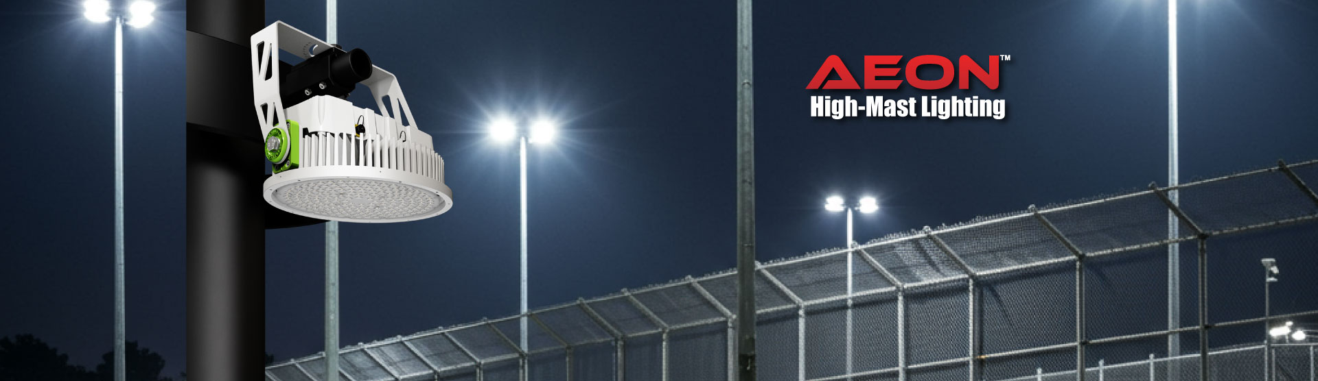
High-mast lighting must provide sufficient light on the target without overlooking what happens beyond it.
Precision optics, calculated property-line points, window vertical surfaces, curfews, and automatic dimming help control offsite light before installation.
High-mast systems operate for decades, requiring robust controls, maintenance accessibility, and surge protection.
A photometric package should be detailed enough for the owner, engineer, contractor, and installer to understand what was calculated. At a minimum, it should identify:
Every high-mast project has different geometry, mounting limitations, performance requirements and environmental conditions. A project-specific layout allows the proposed luminaires, optics, mounting heights and fixture quantities to be evaluated before equipment is selected.
Send AEON your: Site plan • Target areas • Required lighting criteria • Existing/proposed pole info • Mounting heights • Available voltage • Nearby property info • Environmental conditions • Control requirements • Project schedule.
Get help choosing the right AEON LED solution for your field, facility, venue, or outdoor space.